- 您现在的位置:买卖IC网 > Sheet目录370 > ZXLD1371QESTTC (Diodes Inc)IC LED DRIVER
�� �
�
�A� Product� Line� of�
�Diodes� Incorporated�
�ZXLD1371�
�Applications� Information� (cont.)�
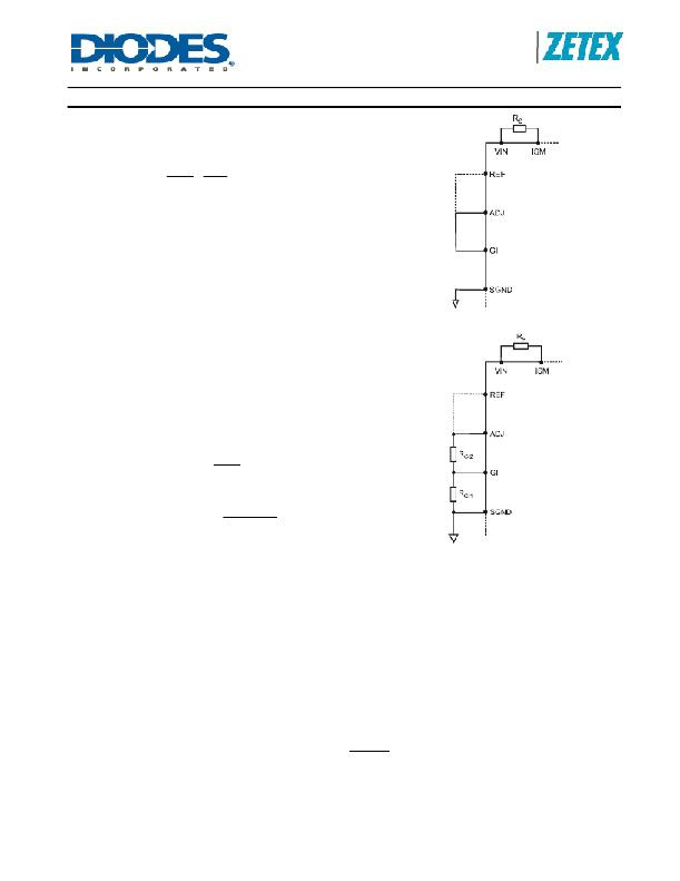
�Buck� topology�
�In� Buck� mode,� GI� is� connected� to� ADJ� as� in� Figure� 5� .� The� LED�
�current� depends� only� upon� R� S� ,� V� ADJ� and� V� REF� .� From� Equation� 1�
�above,�
�R� SBUCK� =� ?� ?�
�?� ?� ?� ?�
�?� ?�
�?� 0 . 218� ?� ?� V� ADJ� ?�
�?� I� LED� ?� ?� V� REF� ?�
�Equation� 10�
�R� SBUCK� =� ?� ?�
�?� ?�
�If� ADJ� is� directly� connected� to� VREF,� this� becomes:�
�?� 0 . 218� ?�
�?� I� LED� ?�
�Figure� 5.� Setting� LED� Current� in� Buck�
�Configuration�
�Boost� and� Buck-boost� topology�
�For� Boost� and� Buck-boost� topologies,� the� LED� current� depends�
�upon� the� resistors,� R� S� ,� R� GI1� ,� and� R� GI2� as� in� Equations� 4� and� 2�
�above.� There� is� more� than� one� degree� of� freedom.� That� is� to� say,�
�there� is� not� a� unique� solution.� From� Equation� 4� ,�
�?� ?� GI� _� ADJ� ?� ?� V� ADJ� ?� ?�
�R� SBoostBB� =� ?� ?�
�?� 0 . 225� ?� ?� ?�
�?� I� LED� ?� ?� V� REF� ?�
�Equation� 11�
�R� SBoostBB� =� ?� ?�
�?� ?� GI� _� ADJ�
�GI� _� ADJ� =� ?�
�?�
�If� ADJ� is� connected� to� REF,� this� becomes�
�?� 0 . 225� ?�
�?� I� LED� ?�
�GI_ADJ� is� given� by� Equation� 2,� repeated� here� for� convenience:�
�?� RGI� 1� ?�
�?� RGI� 1� +� RGI� 2� ?�
�Figure� 6.� Setting� LED� current� in� Boost� and�
�Buck-boost� configurations�
�Note� that� from� considerations� of� ZXLD1371� input� bias� current,� the� recommended� limits� for� R� GI1� are:�
�22k� ?� <� R� GI1� <� 100k� ?� Equation� 12�
�The� additional� degree� of� freedom� allows� us� to� select� GI_ADJ� within� limits� but� this� may� affect� overall� performance� a� little.�
�As� mentioned� above,� the� working� voltage� range� at� the� GI� pin� is� restricted.� The� permitted� range� of� GI_ADJ� in� Boost� or�
�Buck-boost� configuration� is�
�0.2� <� GI_ADJ� <� 0.5� Equation� 13�
�The� mean� voltage� across� the� sense� resistor� is�
�V� RS� =� I� COIL� R� S�
�Equation� 14�
�V� RS� =� 0� .� 225� ?�
�?�
�Note� that� if� GI_ADJ� is� made� larger,� these� equations� show� that� R� S� is� increased� and� V� RS� is� increased.� Therefore,� for� the�
�same� coil� current,� the� dissipation� in� R� S� is� increased.� So,� in� some� cases,� it� is� better� to� minimize� GI_ADJ.� However,�
�consider� Equation� 5� .� If� ADJ� is� connected� to� REF,� this� becomes�
�?� GI _ ADJ� ?�
�?� 1� ?� D� ?�
�This� shows� that� V� RS� becomes� smaller� than� 225mV� if� GI_ADJ� <� 1� -� D.� If� also� D� is� small,� V� RS� can� become� too� small.� For�
�example� if� D� =� 0.2,� and� GI_ADJ� is� the� minimum� value� of� 0.2,� then� V� RS� becomes� 0.225*� 0.2� /� 0.8� =� 56.25� mV.� This� will�
�increase� the� LED� current� error� due� to� small� offsets� in� the� system,� such� as� mV� drop� in� the� copper� printed� wiring� circuit,� or�
�offset� uncertainty� in� the� ZXLD1371.� If� now,� GI_ADJ� is� increased� to� 0.4� or� 0.5,� V� RS� is� increased� to� a� value� greater� than�
�100mV.�
�ZXLD1371�
�Document� number:� DS35436� Rev.� 1� -� 2�
�25� of� 42�
�www.diodes.com�
�February� 2012�
�?� Diodes� Incorporated�
�发布紧急采购,3分钟左右您将得到回复。
相关PDF资料
ZXLD1374EST20TC
IC LED DVR BUCK BOOST 20TSSOP
ZXLD1937ET5TA
IC LED DRIVR WHITE BCKLGT TSOT-5
ZXLD381FHTA
IC LED DRIVR WHITE BCKLT SOT23-3
ZXLD383ET5TA
IC LED DRIVR WHITE BCKLGT TSOT-5
ZXSC300E5TA
IC LED DRVR WHITE BCKLGT SOT23-5
ZXSC380FHTA
IC LED DRVR WHITE BCKLGT SOT23-3
ZXSC400E6TA
IC LED DRVR WHITE BCKLGT SOT23-6
0-1005447-1
SENSOR PIEZO FILM VIBRA MASS
相关代理商/技术参数
ZXLD1374
制造商:DIODES 制造商全称:Diodes Incorporated 功能描述:60V HIGH ACCURACY 1.5A BUCK/BOOST/BUCK-BOOST
ZXLD1374_11
制造商:DIODES 制造商全称:Diodes Incorporated 功能描述:60V HIGH ACCURACY 1.5A BUCK/BOOST/BUCK-BOOST
ZXLD1374EST20TC
功能描述:LED照明驱动器 60V 1.5A BUCK/BOOST LED DRIVER AEC-Q100 RoHS:否 制造商:STMicroelectronics 输入电压:11.5 V to 23 V 工作频率: 最大电源电流:1.7 mA 输出电流: 最大工作温度: 安装风格:SMD/SMT 封装 / 箱体:SO-16N
ZXLD1601
制造商:ZETEX 制造商全称:ZETEX 功能描述:ADJUSTABLE DC - DC BOOST CONVERTER WITH INTERNAL SWITCH IN SC70
ZXLD1601H6
制造商:Diodes Incorporated 功能描述:LCD/OLED BIAS BOOST CONVERTER SMD
ZXLD1601H6TA
功能描述:开关变换器、稳压器与控制器 Boost Converter for LCD and OLED BIAS RoHS:否 制造商:Texas Instruments 输出电压:1.2 V to 10 V 输出电流:300 mA 输出功率: 输入电压:3 V to 17 V 开关频率:1 MHz 工作温度范围: 安装风格:SMD/SMT 封装 / 箱体:WSON-8 封装:Reel
ZXLD1601H6TC
功能描述:开关变换器、稳压器与控制器 Boost Converter for LCD and OLED BIAS RoHS:否 制造商:Texas Instruments 输出电压:1.2 V to 10 V 输出电流:300 mA 输出功率: 输入电压:3 V to 17 V 开关频率:1 MHz 工作温度范围: 安装风格:SMD/SMT 封装 / 箱体:WSON-8 封装:Reel
ZXLD1615
制造商:DIODES 制造商全称:Diodes Incorporated 功能描述:ADJUSTABLE DC-DC BOOST CONVERTER WITH INTERNAL SWITCH IN